Back to my Clock, Watch and Lathe Courses
Answers to questions beyond the scope of this booklet will have to come from your own research. Book stores and libraries are full of excellent books on machining, and the Internet is forming some great user groups that can put you in direct contact with others who share your specific interests. Our own World Wide Web site is a great source of information as well, as we have published there all the instructions for all our tools and accessories for you to read and print out for free. We feel we have written the best book available on miniature machining with Sherline tools. It is called Tabletop Machining by Sherline's owner and long-time toolmaker Joe Martin. We also sell Doug Briney's Home Machinist's Handbook as well as a very informative steam engine project video by Rudy Kouhoupt, both of which are packed with knowledge for new machinists. For the past 35 years I have found Machinery's Handbook to be the source I turn to for answers to my own questions. May your journey toward becoming a skilled machinist be an enjoyable one.
If you are new to machining, you may find it to be either one of the most rewarding skills one can learn or the most frustrating thing you have ever attempted. What makes machining fun for some is the complexity and challenge. The same thing will drive others up the wall. One customer may be overjoyed because he can now make parts that were not available for purchase. Another may wonder why he just spent all day making a part that is similar to one he could have purchased for two dollars. (The difference is that it is not the same as the two dollar part-it is exactly the part needed.)
Machining is a slow process if parts are made one at a time. The interesting thing is, a skilled machinist may take almost as long to make the same part as a novice. Shortcuts usually end in failure. Unlike some other trades, mistakes cannot be covered up. There are no erasers, white-out or "putting-on tools" for machinists; you simply start over. To expand a little on an old rule:
"Think three times, measure twice and cut once!"
The skill in machining isn't just "moving the dials". It is a combination of engineering and craftsmanship. A file is just as useful a tool to a good machinist as a multi-thousand dollar machine tool. Tools "deflect" or bend under load, and anticipating this bend is what it is all about. Sharp tools deflect less than dull tools, but with each pass the tool dulls a little and the deflection becomes greater. If you try to machine a long shaft with a small diameter, the center will always have a larger diameter than the ends because the part deflects away from the tool where it has less support. You can go crazy trying to machine it straight, or you can simply pick up a good flat mill file and file it straight in a few moments. Machine tools will never replace the "craftsman's touch", and machining is a combination of both good tools and good technique.
You should strive from the beginning to make better and more accurate parts than you think you need. Work to closer tolerances than the job demands. Be on the lookout for ways to make a job easier or better. Having a selection of appropriate materials on hand and a good cutoff saw to get them to rough size is a good start. Take some time and read through this instruction book before you try machining anything. We want you to enjoy the process of creating accurate parts from raw metal. Buying a machine didn't make you a machinist, but using it along with the skill and knowledge you acquire along the way eventually will. With the purchase of SHERLINE equipment, you have taken your first step toward many years of machining satisfaction. We at SHERLINE thank you for letting us be a part of that.
Joe Martin
President and Owner
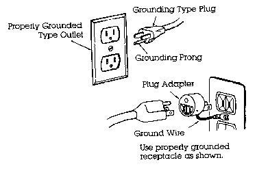
The power cord used is equipped with a 3-prong grounding plug which should only be connected to a properly grounded receptacle for your safety. Should an electrical failure occur in the motor, the grounded plug and receptacle will protect the user from electrical shock. If a properly grounded receptacle is not available, use a grounding adapter to adapt the 3-prong plug to a properly grounded receptacle by attaching the grounding lead from the adapter to the receptacle cover screw.

FIGURE 1-Always use a properly grounded receptacle.
NOTE: The electrical circuits designed into the speed control of your lathe or mill reads incoming current from 100 to 240 volts AC and 50 or 60 Hz. and automatically adapts to supply the correct 90 volts DC to the motor. As long as you have a properly wired, grounded connector cord for your source, the machine will operate anywhere in the world without a transformer. This has been true for all SHERLINE machines built since 1994. Prior to that, we used an AC/DC motor. Use that motor ONLY with the power source for which it was intended. It will not automatically adapt to any other current and using it with an improper power source will burn out the motor or speed control. Also, the first few DC units built did not include the circuits to adapt to other currents. If you have an early DC model, remove the plastic speed control housing and look for a label on the aluminum speed control frame. If it has a small metallic label on top of the frame that lists input voltage as 120VAC, DO NOT ATTEMPT TO CONVERT TO OTHER CURRENTS. Models that can be used with any current have a paper label on the end of the speed control frame which lists the model number as KBLC-240DS.
The machines are normally supplied with a USA type plug but can be easily rewired to accept a European or U.K. type plug by attaching the wires using the color codes provided below.
|
WIRE |
USA |
EUROPE |
|
100/240 V |
BLACK |
BROWN |
|
COMMON |
WHITE |
BLUE |
|
GROUND (EARTH) |
GREEN |
GREEN W/YELLOW |
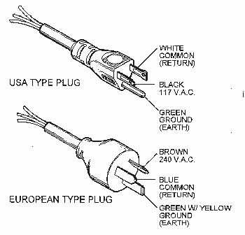
FIGURE1a-Wire color codes for USA and European connectors.
One of the problems with designing and manufacturing metal cutting equipment of this size is that the operator can physically be stronger than the machine, which is not normally the case with larger tools. For example, a 10-pound force applied a couple of inches out on a hex key becomes a 650-pound force at the tip of the screw. If you tighten both screws on the tool post this tight, it becomes approximately 1300 pounds of force on relatively small parts! Tools and/or parts can become distorted and accuracy will be lost. Overtightening hold down screws and T-nuts in their slots can distort the crosslide or mill table. It is not necessary to overtighten parts and tools because loads are smaller on equipment of this size. Save your equipment and increase accuracy by not overtightening and by taking light cuts.
It is also important to realize that you can overload the motor supplied with this lathe or mill.* The many variables involved in machining, such as materials being machined, size of cutter, shape of cutter, diameter of stock, etc., can leave but one rule to follow...COMMON SENSE!
*The motor is thermally protected, so if it is overloaded it will simply shut down until it cools. See note on thermal protection.
Read all operating instructions and safety rules carefully before attempting any machining operations.
Always use care when operating the lathe and mill. Follow safety rules for power tools. Turn off motor before attempting adjustments or maintenance. (Do not simply turn the speed control down to zero RPM but leave the motor switch on.) Be sure the work piece is firmly supported on the lathe or mill. Accessories should be mounted and operated following instructions carefully. Keep your machine clean, lubricated and adjusted as instructed. Do not leave cleaning rags, tools or other materials on the lathe bed or around moving parts of the machine.
Many fine books have been written on machining techniques and are available at your local library or book store. Although these books will be referring to machines many times larger than Sherline's tools, the principle remains the same. For the best reference that is specific to Sherline tools, see Joe Martin's book, Tabletop Machining.
Your new lathe or mill will come packed in a box with some items disassembled for shipping purposes. On the lathe you will install the crosslide table onto the saddle. On the mill you will install the "Z" axis column onto the base. On both machines you will need to install the motor and speed control. The machines are completely assembled and tested for fit at the factory prior to shipping. They are then disassembled and packaged, so everything should go together easily when you reassemble it. The motors are "run in" for approximately one hour to assure proper function and seating of the brushes.
Before you call us and say a part is missing, please look carefully through the packaging. Some parts are in bags taped to the bottom of cardboard flaps or spacers and you may not notice them when you open the box and remove the major components.
Installation of the crosslide requires no tools. First, make sure the bottom of the crosslide has a light coat of grease on all the sliding surfaces. This will have been applied at the factory, just make sure it has not been wiped off and that it is evenly distributed.
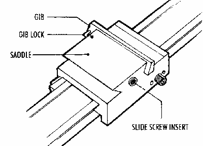
FIGURE 2
Next, see that the gib is in the proper position on the saddle. (See Figure 2.) It is taped into position for shipping. Remove the tape holding it in place. If the gib has come off, position it on the gib lock as shown.
Set the dovetail of the crosslide over the gib and matching dovetail on the saddle. Slide it onto the saddle about 1/4" (6-7mm) until it stops. (See Figure 3.)
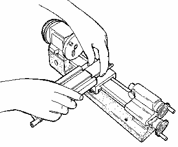
FIGURE 3
Look underneath and align the slide screw with the threads on the brass slide screw insert on the side of the saddle. (See Figure 4.) Turn the crosslide handwheel clockwise to engage the threads. Continue to crank the handwheel clockwise until the crosslide is in the desired position on the saddle.
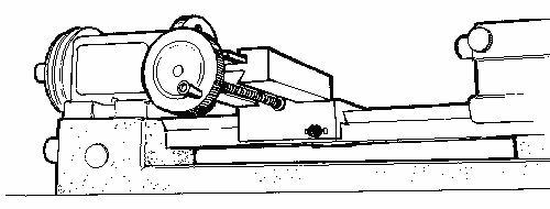
FIGURE 4
The mill is shipped attached to a piece of plywood to keep it from moving in the box. Before you begin, remove the screws holding the mill base to the plywood. It was installed strictly for packing purposes and will need to be removed so that the column can be installed.
The "Z" axis column is mounted to the base with two 1-3/4" long 1/4-20 socket head screws. These screws and the hex key tool you will need to tighten them are packaged in the bag with the motor mounting bracket and drive belt. It is much easier to mount the column to the base before you mount the motor and speed control to the saddle.
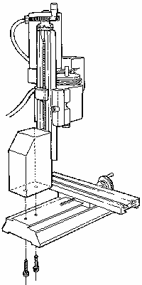
FIGURE 5
Set the column on the base aligned with the mounting holes and hold it in position while you insert the first screw up from the bottom of the base. Hand turn the first screw part way in and then start the second screw. This can be done with the machine upright by letting the base hang over the edge of your table or bench just far enough to expose the first hole. Using the hex key, snug up both screws lightly first, and then tighten evenly.
For specific directions on assembly of the various 8-direction columns and upgrades introduced in August, 1998, click here. The Model 2000 mill and the related upgrades that convert standard mills into 8-direction mills offer the ability to drill holes or do machining operations from an almost infinite number of angles on parts mounted square to the table.
Vibration in shipping can cause some bolts or screws to loosen up. Before using your new machine, check the tightness of all fasteners. It is also a good idea to check tightness periodically when using the machine, as vibration from operation may cause some fasteners to loosen up.
(Refer to the exploded views and number list for part number references.)
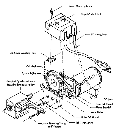
FIGURE 6-DC Motor and Speed Control Assembly
Sherline's 90 volt DC motor is very smooth and powerful, particularly at low RPM. The specially designed electronics package also provides some unique advantages in addition to smooth speed control with a usable speed range of 70 to 2800 RPM. A special circuit compensates for load, helping to keep RPM constant. The machines can also be used on any current world wide from 100 VAC to 240 VAC, 50 or 60 Hz without any further adjustment other than seeing that the proper wall plug is used. The control reads the incoming current and automatically adjusts to the proper settings.
We offer the motor and speed control along with the headstock and spindle as a package to builders of special machinery at a very reasonable price. They are especially popular for custom tooling in small industrial applications because of the large number of Sherline accessories that fit the spindle. We use them in our own production facility for a number of operations.
Thermal protection means there is a built-in circuit breaker that will shut down the motor if it gets too hot. This keeps the motor from burning out. The breaker will automatically reset as soon as the motor cools and you can go back to cutting, but you should be aware of how it works and what to do if the machine suddenly shuts itself down. If your motor is shutting down from overheating on a regular basis, it means you are taking too heavy a cut or operating at too high an RPM for long periods. Slow your speed down, reduce your cut or feed rate and you should have no further problems.
Due to the nature of miniature machining, overloading the machine is a common problem. It is often tempting to try to speed up the process by working faster. Keep in mind this is a small machine and work with patience and precision-don't be in a hurry. Your parts will come out better and your machine will last much longer if it is not overstressed.
If your thermal protection circuit shuts down the motor while work is in progress, immediately shut off the power switch and then back the tool out of the work. It should only take 10 seconds or less for the circuit breaker to reset, then you can turn the motor on and start the cut again, this time putting a little less stress on the motor. If you leave the tool engaged in the part and the power on, when the circuit breaker kicks back on, the motor must start under load. This can be very hard on your motor.
Remember that the circuit breaker turns the speed control off which turns off the motor. If power were to be applied to the speed control with the motor disconnected, it could damage the speed control.
Thermal protection is built into your motor to make sure it is not damaged by overloading. Use good common sense when operating the motor, and it will provide many years of trouble free operation.
The lathe is supplied with an electronic speed control that produces a comprehensive range of speeds suitable for all operations. Special circuitry designed into the DC motor speed control automatically compensates for speed changes due to increased load. If the spindle RPM drops noticeably when cutting, you are taking too heavy a cut. The speed range of the spindle using the speed control is from 70 to 2800 RPM. This is achieved without the inconvenience of changing belt positions or gear ratios as is often the case with other designs. A second belt position is offered as an additional feature to provide extra torque at low RPM for larger diameter parts should your job require it.
To operate the motor, turn the speed control knob counter-clockwise as far as it will go. Then turn the toggle switch to "ON" and select the speed by turning the speed control knob clockwise.
Your new motor should run smoothly the first time you use it as it has been "run in" for about an hour before being shipped to you. Despite our secure packaging, there have been cases where extremely rough handling by a shipper has damaged the magnets in the motor. If the motor does not run when plugged in, turn the motor by hand. If it does not turn smoothly, it may have been damaged in shipment. Call Sherline for instructions on making a damage claim with the shipper. Do not attempt to repair the motor yourself.
You may notice that the post onto which the headstock mounts is a loose fit where it projects from the lathe bed or column saddle. This is normal, and the diagram below will help you understand how it works.

FIGURE 7-Cross section of headstock showing locking screw.
The screw in the front center of the headstock has a cone point. The pivot pin has a tapered slot with a corresponding angle. When the screw is tightened, its angled face engages the groove and, because the pivot pin can not come up, it draws the headstock down into position, clamping it into place. If the pin were rigid, it could keep the headstock from pulling down squarely.
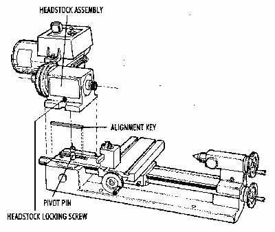
FIGURE 8-Headstock and alignment key in position over lathe.
The headstock is aligned with the lathe bed or column saddle with a precision ground key that fits into keyways in both parts. It is not square in cross section so it will fit in only one direction. Push the headstock firmly against it as you tighten the hold down screw. The mill headstock has two keyways milled into it so it can be mounted in conventional fashion or at a 90░ angle for horizontal milling.
Removing the headstock alignment key allows the headstock to be mounted in positions other than square. This allows you to mill parts at an angle or turn tapers on the lathe. When using the lathe or mill without the alignment key, keep cutting loads light.

FIGURE 9-Machines mounted to a base board for stability.
Mounting the lathe to a board is necessary because of the narrow base. This keeps the machine from tipping. We recommend mounting the lathe on a piece of pre-finished shelf material which should be available from your local hardware store. (See below for sizes.) The machine can be secured to the board using four 10-32 screws with washers and nuts. Lengths should be 1-1/2" for short bed lathes and 1-7/8" for long bed lathes. Rubber feet should be attached at each corner on the bottom of the mounting boards. They are also readily available in hardware stores.
This arrangement gives the machines a stable platform for operation yet still allows for easy storage. The rubber feet help minimize the noise and vibration from the motor. Mounting the tool directly to the workbench can cause vibration of the bench itself which acts as a "speaker" and actually amplifies the motor noise. Bench mounting also eliminates one of the best features of Sherline machines...the ability to easily be put away for storage.
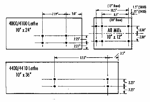
FIGURE 10-Plans for mounting board hole patterns. Confirm actual dimensions from your lathe or mill before drilling. The newly added model 2000 multi-direction mill can be mounted to a board 12" x 18" in a similar fashion.
The mill may be mounted in a similar manner on a 10" x 12" to 12" x 24" pre-finished shelf board with rubber feet using 10-32 x 1" screws to attach the mill to the board.
To keep your Sherline tools clean, soft plastic dust covers are available. The lathe cover is P/N 4150 for the Model 4000/4100 and 4500/4530 short bed lathes and P/N 4151 for the Model 4400/4410 long bed lathe. A mill dust cover is available as P/N 5150.
All Sherline tools and accessories are manufactured in your choice of inch or metric calibrations. Converting a lathe or mill from one measurement system to the other is possible, but it takes more than changing the handwheels. The leadscrews, nuts and inserts must also be changed. A look at the exploded views of the machines on pages 27 and 28 will show which parts need to be purchased. (Look for parts that have both a metric and inch version in the parts listing.) Conversion kits with all the necessary parts are available. If you are a good mechanic, you can do the conversion yourself, or you can return your machine to the factory for conversion.
The normal pulley position, which is placing the belt on the larger motor pulley and smaller headstock pulley, will suffice for most of your machining work. Moving the belt to the other position (smaller motor pulley, larger headstock pulley) will provide additional torque at lower RPM. It is particularly useful when turning larger diameter parts with the optional riser block in place.

FIGURE 11-The two pulley positions. Position A is the conventional setting, position B offers more torque at low RPM. (Seen from pulley end of headstock.)
To change the pulley position, remove the speed control hold down screw and pivot the speed control housing up out of the way. Remove the mounting plate from its position on the rails of the two halves of the belt guard housing. Loosen the two nuts that hold the motor to the motor mounting bracket and take the tension off the belt. With your finger, push the belt off the larger groove of the pulley and into the smaller one. (Depending on which way you are changing it, this could be either the motor or spindle pulley.) Then move the belt to the larger diameter groove on the other pulley and rotate the headstock by hand to get it to seat. Push the motor outward on the motor mounting bracket to put the proper tension on the belt and retighten the two motor mounting screws. Now you can replace the mounting plate, pivot the speed control back down and refasten it. Moving the belt back to the other position is simply a reverse of the above procedure.
SPINDLE ADJUSTMENT
-If any end play develops in the main spindle, it can be easily eliminated by readjusting the preload nut. (See part number 4016 in the exploded view.) When the headstocks are assembled at the factory, the preload nut is adjusted to .0002" (.005mm) of end play. This is controlled by the outer races of the bearing being held apart by the headstock case and the inner races being pulled together by the preload nut. This setting was determined through experience and, like everything in engineering, it is a compromise. If the machine is only to be run at high speed, this setting may be too "tight". The headstock will run fairly warm to the touch normally, but extended periods of high speed operation may bring about excessive temperature. If this is your case, the preload may be reduced slightly.To change the adjustment, remove the spindle pulley, loosen the set screw in the preload nut and back the preload nut off four degrees of rotation (counter clockwise). The bearings are lightly pressed into the case, so the inner race will not move without a sharp tap with a plastic mallet to the end of the spindle where the pulley is attached.
If you find your bearings are set too loose, you may want to take up on the end play. You can check them with an indicator or by spinning the spindle without the motor belt engaged. If the spindle spins freely with a chuck or faceplate on it, it is too loose for normal work. Adjust the preload nut until it turns approximately one and a half revolutions when spun by hand.
Gibs (tapered synthetic adjustment shims) are fitted to the mill headstock, saddle and table and to the lathe saddle and crosslide. Correct adjustment of the gibs will ensure smooth and steady operation of the slides. The gib is effectively a taper with an angle corresponding to the one machined into the saddle. It is held in place by an "L" wire gib lock which is secured with a locking screw. It is adjusted by loosening the gib locking screw and pushing the gib in until "play" is removed. After adjusting, retighten the locking screw. Milling operations require a tighter adjustment of the gibs than lathe operations.
Backlash is the amount the handwheel can turn before the slide starts to move when changing directions. This is a fact of life on any machine tool and on machines of this type it should be about .003" to .005" (.08mm to .12mm).
Backlash must be allowed for by feeding in one direction only. Example: You are turning a bar to .600" diameter. The bar now measures .622" which requires a cut of .011" to bring it to a finished diameter of .600". If the user inadvertently turns the handwheel .012" instead of .011", he couldn't reverse the handwheel just .001" to correct the error. The handwheel would have to be reversed for an amount greater than the backlash in the feed screws before resetting the handwheel to its proper position.
Backlash on the "X" and "Y" axes of the mill may be reduced to a minimum by adjustment on the anti-backlash nuts. These nuts are located on the handwheel ends of the mill saddle. The nuts are secured by slotted pan head screws which hold a pointed locking plate that interlocks with teeth on the nut.
To adjust backlash, simply loosen the pan head screw and slide the locking plate to one side. Rotate the anti-backlash nut clockwise on the "X" axis and counterclockwise on the "Y" axis until snug. Replace the locking plate and tighten the pan head screw. With the anti-backlash nuts properly adjusted, the lead screws will turn smoothly and have no more than the proper .003" to .005" of backlash.
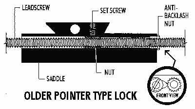
FIGURE 12-Backlash Adjustment. NOTE: A new lock now uses a star gear rather than the pointer to locate the anti-backlash nut, and a button head socket screw locks it in place. This system is easier to use, but the function is essentially the same. (The hole centers are different, which means the star gear cannot be used to replace the pointer on older models.)
The handwheels are secured to their corresponding leadscrew shafts by a small set screw in the side of the handwheel base. Check them periodically to make sure they have not been loosened by vibration. On the "zero" adjustable handwheels, you must first release the rotating collar by loosening the locking wheel. Then rotate the collar until you can see the set screw through the small hole in the side of the collar and adjust the screw as necessary.
If excessive backlash develops at the handwheel and thrust collar junctions, adjust by first loosening the handwheel set screw. Index (rotate) the handwheel so the set screw tightens on a different part of the shaft. (If you don't, it may tend to keep picking up the previous tightening indentation and returning to the same spot.) Push the handwheel in tightly while holding the mill saddle and retighten the handwheel set screw.
Turning the appropriate handwheel moves the saddle, crosslide and tailstock spindle. For the inch version, one complete turn of the handwheel gives a movement of .050". For the metric model, one complete turn of the handwheel gives a movement of 1mm. Handwheels are calibrated in .001" (1/1000") for inch models and .01mm (1/100mm) for metric models. Keep the screws clean, oiled and free from chips. The handwheels are quite accurate and should be used accordingly.
The versatile feature of Sherline machines that allows the headstock to be removed or rotated for taper turning and angle milling keeps us from being able to lock the headstock in perfect alignment. Precision ground alignment keys and accurate adjustment at the factory, however, make the machines highly accurate. In standard form, alignment should be within .003" (.08mm). This should be more than acceptable for most jobs you will attempt.
Only someone new to machining would talk about "perfect" alignment. Machinists speak instead in terms of "tolerances", because no method of measurement is totally without error. We believe the tolerances of your machine are close enough for the work for which it was intended, however, for those searching for maximum accuracy, here are some tips for maximizing the accuracy of your machine.
Loosen the headstock, push it back evenly against the alignment key and retighten. This will maximize the accuracy of the factory setting. To achieve greater accuracy, you will have to be willing to sacrifice one of the better features of your lathe or mill; that is, its ability to turn tapers and mill angles in such a simple manner.
HEADSTOCK
-If you choose total accuracy over versatility or need it for a particular job, proceed as follows. Remove the headstock and clean any oil from the alignment key and slot and from the area of contact between bed and headstock. Replace the headstock, pushing squarely against the key and retighten. Take a light test cut on a piece of 1/2" to 3/4" diameter by 3" long aluminum stock held in a 3-jaw chuck. Use a sharp pointed tool to keep cutting loads low so as not to cause any deflection of the part. Measure the diameter of both machined ends. If there is a difference, the headstock is not perfectly square. Now, without removing the key, tap the headstock on the left front side if the part is larger at the outer end. (Tap on the right side if the part is larger at the headstock end.) You are trying to rotate the headstock ever so slightly when viewed from the top until the machine cuts as straight as you can measure. There should be enough movement available without removing the key, as its factory placement is quite accurate.Take another test cut and remeasure. Repeat this procedure until you have achieved the level of perfection you seek. Then stand the lathe on end with the alignment key pointing up and put a few drops of LocTite™ on the joint between key and headstock. Capillary action will draw the sealant in, and when it hardens, the key will be locked in place. We prefer this method to "pinning" the head with 1/8" dowel pins, because it offers you the option to change your mind. The headstock can be removed by prying with a screwdriver blade in the slot between the bottom of the headstock and the lathe bed to break the LocTite™ loose should you wish to be able to rotate the headstock again.
TAILSTOCK
-To maximize the machine's tailstock alignment, first make sure that there are no chips caught in the dovetail of the bed and no chips or dents in the taper of your tailstock center. Now put a 6" long piece between centers and take a long, light test cut. Measurements at either end will tell you if you need to use an adjustable tailstock tool holder in the tailstock to achieve better tailstock alignment. We manufacture adjustable tailstock tool holders (P/N 1202 & 1203) and an adjustable live center (P/N 1201) which can help you attain near perfect alignment at the tailstock should your job require it. Instructions for their use are included with each item.Remember that unless you drill very small holes (less than 1/64") or turn a lot of long shafts, you are giving up a very useful feature to solve a problem which can usually be handled with a few passes of a good mill file. The inaccuracy inherent in any drill chuck is such that perfect machine alignment is meaningless unless you use adjustable tailstock tool holders.
Much can be written about the use of lubricants, but they may usually be dispensed with where production rates are not very important. A small amount of any kind of oil applied with a small brush will be sufficient. Aluminum and its alloys may require the use of cutting oils to prevent the chips from welding to the tool's point. Do not use oils with a low flash point or a bad smell. If desired, a mixture of one part soluble oil to six parts water may be used on steel to assist in producing a smoother finish and reduce tool chatter when parting off. Brass and cast iron are always turned dry. Cutting lubricants should be cleaned off the tools after use.
Cutting oils can be purchased at an industrial supply store. We used to sell cutting oil, but dropped it from the line because we received so few orders. We assume our customers prefer to purchase their cutting oil from local sources. Do not use high sulfur pipe thread cutting oil. It is good for hard to machine materials, but is so dirty to work with we do not recommend it. We also find some of the tap cutting fluids are too smelly and unpleasant to use for general machining.
The main purpose of using lubricants is to keep the chips from sticking to the cutting tool. When used properly, modern high speed tool bits are not likely to be affected by heat on the type of work usually done on Sherline tools.
Two terms frequently used in machining are "Feed" and "Cut". Reference to the diagrams below will show what is meant by these terms. Normal turning on a lathe, when used to reduce the diameter of a work piece, involves advancing the cutting tool perpendicular to the lathe bed by an appropriate amount (depth of cut) and feeding the tool along parallel to the lathe bed to remove material over the desired length. (See Figure 13A below.)
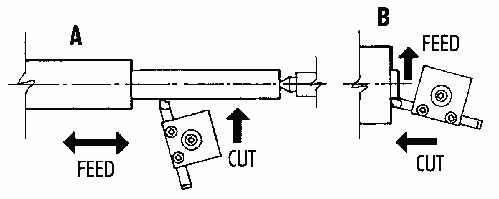
FIGURE 13-Directions of Feed and Cut showing (A) Turning work between centers and (B) Facing off a work piece.
In normal machining, the depth of cut is set by the crosslide handwheel, and the feed is provided by the handwheel on the end of the bed. When facing off the end of a work piece held in a chuck or faceplate, the depth of cut is set by the handwheel on the end of the bed, and the feed is provided by the crosslide handwheel. (See Figure 13B above.)
When using a mill, cut is determined by the amount of depth the cutter is set to by the "Z" axis handwheel. Feed is supplied by either or both the "X" or "Y" axis handwheels depending on the desired direction of the cut.
Before attempting to machine any metal, please try to remember this simple rule about machining:
Understanding this simple rule can save you many hours of grief. When the tool "chatters", it is not cutting in a continuous fashion. Metal likes to be machined in a way that allows the material to come off in a continuous strip while the tool is in contact with the metal. If the tool is not fed at a rate that is fast enough, the tool skips along the surface, occasionally digging in. The surface of the tool that is doing the most cutting will find a frequency of vibration that is a product of all the variables involved. This can cause anything from a high pitched whine on light, high speed cuts to a resonating racket that can rip the work out of the chuck on heavy cuts. If you maintain the same feed rate and reduce the RPM, the feed will increase because chip will be thicker. (If that sounds wrong at first, think of it this way: At the same feed rate, if you cut the RPM in half, twice as much metal must be removed with each rotation to get to the end of the cut in the same amount of time. The chip is twice as thick, so the feed is GREATER at lower RPM if the feed RATE stays constant.)
When a tool chatters it gets dull faster because it must keep cutting through the previously machined surface that has been "work hardened" by machining. As you can imagine, there are limits to how much you can increase feed rate, so the answer lies in adjusting both speed and feed to achieve the proper cut.
Proper cutting speed is the rate a particular material can be machined without damaging the cutting edge of the tool that is machining it. It is based on the surface speed of the material in relation to the cutter. This speed is a function of both the RPM of the spindle as well as the diameter of the part or size of the cutter, because, as the part diameter or cutter size increases, the surface moves a greater distance in a single rotation. If you exceed this ideal speed, you can damage the cutting tool. In the lathe and mill instructions, we give some examples of suggested cutting speeds, but what I wanted to get across here is that it isn't a slow process. A tool can be destroyed in just a few seconds. It isn't a case of getting only one hour of use instead of two. The cutting edge actually melts. If you machine tough materials like stainless steel, you will ruin more tools than you care to buy if you don't pay a lot of attention to cutting speeds. Charts showing suggested cutting speeds for various materials are included in both the lathe and mill sections that follow. See the links below
BR> Go to Lathe Instructions SectionRETURN TO ACCESSORIES MASTER LIST
Shop for Sherline LATHES
Shop for Sherline MILLING MACHINES
RETURN TO My Home Page
| Home
Page | Frequently
Asked Questions | Testimonials
| Lathes
|
| Mills
| Accessories
|
Tool
Prices | Accessory
Prices |