CAUTION! |
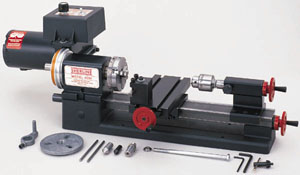
FIGURE 1--Parts of a Sherline lathe (Note: Tailstock locking screw is now relocated to a vertical position on the newer tailstocks. This drawing shows an older style tailstock without gib or cutout front face.)
Each type of turning work requires the correct tool for the job. It is important that the cutting tool is sharp and correctly set up in the tool post. The cutting edge of the tool should be exactly level with the center height of the lathe. Check this against either the headstock center or tailstock center. We also manufacture a simple tool height adjustment gauge (P/N 3009) which allows you to check tool height at any time by measuring from the table surface.
FIGURE 2—Leveling the tool using (A) the tip of a head- or tailstock center or (B) Sherline's tool height gauge P/N 3009. The standard tool post shown comes with 4000-series lathes. The 4400-series lathes come with an upgraded rocker tool post that allows the tip of the tool to be adjusted up or down without shimming.
The standard Sherline tool post is designed to hold common 1/4" square tool bits which have had a few thousandths of an inch (.1mm) ground off the top edge for sharpening. Loosen the hold-down bolt and slide the tool post as close to the center as possible. The tip of the tool bit may be raised or lowered by sliding a shim* underneath it. The cutting edge must be on center or just below center (0.004" or .01mm maximum). Ensure that the tool is fixed securely in position by firmly tightening the socket head screws. Try not to have the tool cutting edge protruding more than 3/8" (10mm) from the tool post.
*NOTE: Thin metal shim stock can be used for this purpose. If you don't have any metal thin enough, a single thickness of paper business card stock will usually do the job. Do not use more than one thickness as it will compress too much. Our optional rocker tool post (P/N 3057) allows this adjustment to be made without shims. It comes standard with the Model 4400/4410 long bed lathe.
If you have never operated a lathe before, we suggest that you make a trial cut on a scrap of material to learn the operation of the machine. In a 3- or 4-jaw chuck, secure a piece of round aluminum stock approximately 3/4" (19mm) diameter and 1-1/2" (38mm) long. Secure the presharpened 1/4" square cutting tool supplied with the lathe in the tool post, making sure that it is properly positioned. Turn the speed control all the way counterclockwise, and then turn the motor on. Bring the speed up to approximately 1000 RPM (about 1/3 speed). To establish tool position in relation to the work, bring the tool in slowly until it just starts to scribe a line on the work. Crank the tool towards the tailstock until it clears the end of the work. Advance the tool .010" (.25mm) using the crosslide handwheel (10 divisions on the inch handwheel scale). Using the bed handwheel, move the tool slowly across the work toward the headstock.
Cutting tools used on lathes are designed to remove metal much as paper is removed from a roll. It takes a positive feed rate to accomplish this. If the feed rate isn't fast enough, it would be similar to tearing an individual sheet of paper off the roll. The results when cutting metal would be shorter tool life, a poor finish and tool "chatter". Chatter is a function of rigidity, but it is controlled by speed (RPM) and feed rate.
Since you already have a piece of aluminum chucked up, experiment with speed and feed rate. You just took a cut of .010" (.25mm) and probably noticed that the machine didn't even slow down in the slightest. Now take a 1/2 inch long cut .050" or 1mm deep, which is 1 revolution of the handwheel. If you used the sharpened cutting tool that came with your machine it should have made the cut easily. If the tool "squealed", reduce the RPM a little and take another .050" cut while feeding the tool faster. You will probably be surprised at how easily your machine takes cuts this heavy.
We will now purposely try to make the machine "chatter". Make sure the stock you are cutting is sticking out of the chuck no more than 1 inch (25mm). Crank the handwheel two turns further in from the last setting which will give you a .100" (100 thousandths of an inch) or 2mm cut. Set the spindle speed to about 1000 RPM (1/3 speed) and feed the tool slowly into the material. Vary speed and feed until you get a substantial chatter. Without changing the depth of the cut, drop the speed to about 200 RPM and feed the tool into the work with more force. The chatter should disappear. Once you have learned to control chatter by adjusting speed and feed, you will be on your way to becoming a machinist.
Work can be held between centers, in three- or four-jaw chucks, on the faceplate or with a collet. Sometimes it is necessary to use a chuck and center, and, if the work is spinning fast, a live center should be used. (See Figures 3 and 4.)
FIGURE 3—Holding a round work piece in a 3-jaw chuck.
FIGURE 4—Holding a square work piece in a 4-jaw chuck. .
This is done by fitting the dog to the work that is to be turned and placing the work and dog between the centers in the headstock and tailstock. The maximum diameter that can be held with the dog is 5/8" (15mm). (See Figure 5.)
FIGURE 5—Turning between centers with a faceplate and drive dog.
The dog is driven by fitting it into one of the faceplate holes. This method of turning is ideal for bar work or turning of steps on a bar. The tailstock center must be greased to prevent overheating. (An optional "live center"—such as P/N 1191—turning on ball bearings is the solution preferred by most machinists.) The headstock spindle has a Morse No. 1 taper in the spindle nose. The spindle thread is 3/4-16 TPI. Accessories held in the spindle using the Morse No. 1 taper can be removed with the use of a knockout rod (not supplied) approximately 3/8" diameter and 6" long. The bar is inserted through the back of the spindle, and accessories, such as centers, can be removed with a few taps. The tailstock spindle is equipped with a Morse No. 0 taper and accessories such as drill chucks and centers can be removed by turning the handwheel counterclockwise until the accessory is ejected.
Because the work turns and the drill does not on a lathe, it is necessary to use a center drill before a standard drill can be used. Due to the flexibility of a standard drill bit, it will tend to wander on the surface of the rotating work whereas a center drill is designed to seek the center and begin drilling. Cutting oil is recommended for all drilling operations. A center drill should be withdrawn, cleared of chips and oiled several times during the drilling of a hole to keep the tip from breaking off.
FIGURE 6—Center drilling. The work turns while the drill is stationary.
See chart of commonly available center drill sizes.
FIGURE 7--Center drilling a long work piece held in a steady rest.
Hold the work in a 3- or 4-jaw chuck. If the work is longer than approximately 3" (76mm), support the free end with a steady rest. Fit the drill chuck to the tailstock with a No. 0 Morse arbor and secure a center drill in the chuck. Adjust the tailstock to bring the center drill close to the work and lock in position. Turn the tailstock handwheel to bring the center drill forward. After the hole is started with the center drill, switch to a standard drill bit of the desired size to drill the hole.
The drill chuck comes fitted with a #0 Morse arbor that fits in the tailstock spindle. To use it in the headstock you will need to first change to the #1 Morse arbor which is included with your lathe. To change arbors, put the drill chuck key in its hole to give you better purchase to grip the chuck while using a wrench to remove the #0 arbor and replace it with the larger #1 arbor. Put the drill chuck in the headstock. Then put the drawbolt with its washer through the spindle hole from the other end of the headstock and tighten the drawbolt. DO NOT OVERTIGHTEN! (To remove, loosen the drawbolt a little and give it a light tap with a plastic mallet to break the chuck loose from the taper before completely removing the drawbolt.)
FIGURE 8—Headstock Drilling. The drill turns while the work is held stationary.
The easiest way to center drill the end of a round shaft which has a diameter too large to be put through the spindle is to support it with a steady rest (P/N 1074) while the end is being drilled. If this isn't possible, find the center with a centering square, prick punch a mark and center drill by hand. (See accessories, page 16. See also our Tools and Accessories Catalog for a photo of the steady rest in use.)
Twist drills will generally not drill perfectly accurate sizes, and very small boring tools are not satisfactory in deep holes because of their flexibility. Therefore, reaming is used for holes requiring accuracy within .0005" (.013mm). Reamers are available in any standard size but are rather expensive and are generally not purchased to do one-of-a-kind type work. Use them only when a boring tool cannot be used because of the depth of the hole. Because of their length, they cannot always be used on a small lathe.
Reamers are used only to "clean up" the hole. To make an accurate hole, the work is drilled approximately .010" (.25mm) smaller than the reamer size. The work should be slowly rotated and the reamer slowly fed into the hole while applying plenty of cutting oil. The reamer should be frequently removed and cleared of chips. Never rotate a reamer backwards in the work as this can dull the cutting edges.
The faceplate has three slots which allow work to be bolted to its surface. Flat work can be screwed directly to the faceplate. Extra holes can be drilled to suit odd shaped work unsuitable for a chuck. If the work is mounted off center, be sure to counter balance the faceplate and use very low RPM. Don't hesitate to drill holes in or modify the faceplate as needed to do a particular job. That's what they are for. They are inexpensive and you can have several on hand modified for special jobs.
On most lathes a taper can be cut by offsetting the tailstock. On the Sherline lathe it is done by removing the headstock key and turning the headstock to any angle away from dead center. To rotate the headstock, the alignment key must first be removed. Loosen the set screw in the front of the headstock and lift the headstock and motor unit off the locating pin. Tap the alignment key out of its slot on the bottom of the headstock and replace the headstock unit on the pin. While pressing down on the headstock, rotate it to the angle you desire by referring to the angle scale on the bed. The base is calibrated in 5° increments up to 45° both left and right of dead center. When set to the proper angle, retighten the set screw against the pin to lock the headstock into position. The compound slide (P/N 1080) is another tool that makes taper tuning easy. (See Figure 6, Pages 11/12 in Sherline's Tools and Accessories Catalog for a photo.)
FIGURE 9--Turning a taper with the Headstock rotated.
Short work can be inserted in a 3- or 4-jaw chuck and turned as shown in Figure 9. If the headstock is angled towards the lathe front, the taper will cut smaller at the right. Tapers can also be bored in work held in the 3- or 4- jaw chuck. To machine a taper in longer stock, center drill both ends of the bar, set the headstock angle and mount the part between centers. (See Fig. 10.)
FIGURE 10—Long, shallow tapers can be cut in a continuous pass by pivoting the headstock to the proper offset while supporting the other end with the tailstock. The work is driven by using a drive dog in the faceplate. The dog acts like a "universal joint" as the drive pin slides in the faceplate slot.
The shaping of cutting tools to suitable angles for the type of material and nature of work being performed can be very important to satisfactory work. When tools become dull, gently re-grind and preserve the original angles and shapes. Do not grind the top face of the tools, but confine sharpening to the end and/or sides except form tools which are ground on the top surface.
Remember that heavy cuts and rapid feed will cause greater strain on the chuck and lathe. This may induce "spring" or binding of work and tools which can produce a poor finish.
NOTE: Because of the importance of a sharp and properly ground tool to the cutting process, Sherline has prepared a special instruction sheet on Grinding Your Own Lathe Tools. There are a few tips that can make the process a simple one. The instructions are included with each lathe and with cutting tool sets when you order them from us, or you may call us and request a copy. (Cost is $5.00 postage paid.) They are also available from our World Wide Web site by clicking on the highlighted words above.
FIGURE 11—Tool Shapes.
*These shapes are available in high speed steel tool set, P/N 3007.
**The 60° threading tool is included as part of the carbide tool set, P/N 3006 and also comes with the thread cutting attachment, P/N 3100.
***The parting tool comes with the cutoff tool holder, P/N 3002. Other shapes are custom ground to accomplish special purposes as needed.
Cutting tools are ground to various shapes according to their usage. Tools are usually ground to shape as needed by the operator. Some standard tools are described below:
Normal Turning Tool—This feeds from right to left, is used to reduce work to the desired diameter and is the most frequently used of all tools.
Side Tools—These are used to face off the ends of shoulders and may also be used as normal turning tools. Note that a tool which is fed from LEFT to RIGHT is called a LEFT side tool.
Parting —The conventional parting tool is shaped like a dovetail when viewed from above and is used to cut off work pieces by feeding the end of the tool across the lathe bed and through the work piece. The
Sherline parting tool instead uses a thin .040" (1mm) blade which has a slightly thicker ridge at the top to accomplish the same job of providing clearance for the tool while cutting. Parting tools thicker than .040" (1mm) will be too thick for use on your
Sherline lathe.
Boring Tool—Used in the tool post on a lathe or in an offsettable boring head on a mill to enlarge holes in a work piece.
FIGURE 12—A Boring Tool in use.
Form Tool—A custom contour can be ground into a tool to produce a special shape like a radius in a part. The width of the cutting edge must be less than 2-1/2 times the smallest diameter. Cutting speed must be slow to prevent chatter.
FIGURE 13—Form tool and the part it shapes.
The clearances ground behind the cutting edges indicate the type of material for which the tool may be used and the direction in which it is fed along the work. When grinding tool bits, correct clearances are essential or "rubbing" can occur.
Turning Tools (left and right hand)—Reference to Figure 11 will illustrate the lateral positioning of this tool. Note the clearance behind the point between the end of the tool and the work. Insufficient clearance will cause the tool to "rub" and excessive clearance will produce a ridged or wavy finish due to the small length of tool edge in contact with the work. This ridging becomes more pronounced with rapid feed. To provide a smooth finish, the sharp cutting point may be slightly rounded with an oilstone, taking care to preserve the side clearance underneath this corner.
FIGURE 14—Arrows show direction of tool feed in all diagrams.
This tool should not be advanced directly endwise into the work. The depth of cut is set while the tool is clear of the end of the work. The starting procedure is to advance the tool until the point just touches the work. Note the reading on the crosslide handwheel, withdraw the tool slightly and move along until clear of the end of the work. Now advance the crosslide to the above reading, add desired depth of cut and then feed the tool along the work piece the desired distance. Withdraw the tool clear of the work, having noted the reading on the crosslide handwheel, mentally note the reading on the lead screw handwheel, return the tool to starting position and advance to the previous reading plus the desired cut.
(Note: Sherline offers optional adjustable "zero" handwheels which allow you to reset the handwheel to zero...a handy feature often found only on expensive full size machine tools.)
The second feed is now commenced, ceasing at the same previous reading of the lead screw handwheel. This procedure enables turning to accurate length.
Repeat the procedure until the work has been reduced to within about .010" (0.25mm) of desired diameter, noting that each .015" (0.4mm) increase in depth of cut will reduce the work diameter by twice this amount; that is, .030" (0.8mm). For the finishing pass, advance the tool by the required amount and feed along the work just far enough to gauge the finished diameter. Adjust depth of cut if necessary and complete the final pass using a SLOW feed to obtain a smooth finish and exact size.
After completing a part in the lathe it is frequently necessary to separate the part from the excess material used for chucking. This operation is best accomplished with the use of a cutoff tool or "parting tool" as it is sometimes called. The Sherline cutoff tool and holder (P/N 3002) utilizes a very slender, high speed tool steel cutting blade mounted in a special tool holder. The thinness of the blade (.040") enables it to feed into the part quite easily and at the same time minimizes the amount of waste material. One word of caution; never use a parting tool on a part mounted between centers. The part may bind on the cutter and result in a scrapped part or a broken cutting tool.
FIGURE 15—A parting tool used to separate a part from it's workpiece.
Always try to lay work out so the cutoff tool is used as close to the spindle as possible. Set blade height by sliding the blade in its slot in the tool holder. It should be set so the tip is aligned with the centerline of the part being cut. An unusual diameter may require a shim under the front or rear of the holder to accomplish this. The tool can also be mounted on the back side of the table by using the rear mounting block, P/N 3016.
NOTE: A rear mount cutoff tool is now available that allows the parting tool to be left in place on the rear side of the part for quick use. The parting tool is held upside down in the holder. See P/N 3018.
NOTE: ALWAYS USE CUTTING OIL WHEN USING THE CUTOFF TOOL. The cut will be made much smoother, easier and cooler.
The turning speed for parting should be about one half the normal turning speed and feed rate should be a little heavy so the chip will not break up in the slot. If speed and feed are correct, there will not be any chatter, and the chip will come out as if it were being unrolled. Cutting oil plays a major roll in this occurring properly.
If the tool chatters, first check to see if the work is being held properly. Then decrease speed (RPM) or increase feed rate or both. Once the blade has chattered, it leaves a serrated finish that causes more chatter. Sometimes a serrated finish can be eliminated by stopping the spindle, adding a liberal amount of cutting oil, bringing the blade up so there is a slight pressure on it without the spindle turning, and then turning by hand or as slowly as possible with the speed control.
Very small work may be completely cut off when held in a chuck and allowed to fall onto the crosslide. It is too small and light to cause any damage. Hollow articles, such as rings, may be caught on a piece of wire whose end is held in a suitable position.
While these may be, and often are, used as general purpose turning tools, their specific use is for facing the sides of collars and shoulders; that is, finishing these to correct dimension and with a smooth, flat surface. They are also for facing work held on a faceplate or in a chuck. The facing of work in this manner is very useful for the production of truly flat surfaces and for producing articles to an exact thickness. The two uses of the side tools are illustrated in Figure 11 and 14. The sharp corner at the cutting point should not be slightly rounded, as may be done with the normal turning tool, as knife tools may be required to produce sharp corners.
The use of this tool requires the existence of a drilled or cored hole, or it may be used to enlarge the bore of a tube. The work must be mounted in a chuck or on a faceplate and the boring tool set as shown in Figure 24. Note the clearance behind the cutting point as shown in Figure 16 below.
FIGURE 16--Boring tool clearance.
A slow rate of feed should be used as the turnings are not able to escape freely from the hole. Frequent withdrawal of the tool to allow turnings to escape may be necessary. Care should be taken not to feed the tool beyond the depth required or to feed so deeply as to damage the chuck or faceplate.
Where a hole must be bored right through the work, it should be shimmed out from the faceplate to provide clearance for the tool to feed through. The lead screw handwheel graduations can be used to indicate the correct depth at which to stop the feed. Notice that with boring, the depth of cut is increased by moving the tool and crosslide towards the operator and not away as with normal turning.
The boring of holes often necessitates greater than normal overhang of the tool from the tool post, so the depth of cut and rate of feed should be reduced from normal.
Sherline brings the home shop machinist into the space age with cutting tools that add a new dimension to small lathes. When working with tough metals, high speed steel tools need constant sharpening and have a relatively short life. Brazed carbide tools cut great but chip easily. Inserted carbide cutting tools are the answer and have replaced those other tools in the modern machine shop. Carbide inserts have the ability to consistently give good finishes and long tool life at a much higher cutting speed. This is especially important with small lathes because they do not have excessive power at low RPM. With inserted carbide tools you can cut stainless steel at the same RPM you were formerly using to cut aluminum with high speed steel tools without any sacrifice in quality in surface finish.
FIGURE 17--A Carbide Inserted Tip Cutter installed on the tip of a special tool designed to hold them.
These tools are more expensive than high speed steel; however, they are worth every penny if you have problems grinding your own steel tools or are cutting exotic materials like stainless steel. Sherline offers a tool post ( P/N 7600) which holds the larger 3/8" diameter tool shanks used to hold carbide or diamond inserted tips. It also has a 3/8" round hole for boring tools. A good starting point for a tool is the P/N 7615 right hand holder that uses the P/N 7605 insert. This is a 55° insert good for turning, facing and profiling. Also available are 80° inserts which are slightly less versatile but offer longer tool life because of their stronger, more square shape. These tools should not be used to cut hardened steels or piano wire. Materials such as those should be ground to shape, not cut. Abrasive materials such as glass reinforced plastics can be easily cut with these tools.
FIGURE 18—3/8" Negative rake insert tool holder (P/N 7610).
Another tool available to Sherline machinists which holds carbide inserts is the 3/8" IC 55° negative rake insert tool holder (P/N 7610). The indexable carbide insert sits on the tool holder at a 5° negative angle. This gives the sides of the cutter clearance even though the insert has square sides. By having square sides, both top and bottom of the insert can be used as cutting edges, giving a total of four cutting edges on each insert. Because of its design, it cuts like a positive rake cutter which requires less rigidity than a negative rake cutter. It gives you the best of both worlds—the four cutting edges of a negative rake tool along with the lower stress loading of a positive rake cutter which is appropriate for a lathe of this type.
FIGURE 19—Negative and Positive Rake Carbide Cutting Tips. Negative Rake tips can be held upside down giving 4 cutting edges. Positive Rake tips cut from one side only, but cut better.
When searching for a mirrorlike finish on copper or aluminum, a four-sided diamond insert (P/N 7609) and a tool holder (P/N 7619) are also available. Though expensive, the four cutting edges of the diamond insert mean you are really getting four tools in one, making it a better deal than it may first appear.
NOTE: Never attempt to cut steel with a diamond cutter.
While inserted tip carbide and diamond cutting tools will improve the performance of the Sherline Lathe, they will not correct poor machining technique. Rigid setups are a must for tools such as these.
FIGURE 20—The Sherline W.R. Smith T-Rest
Another method of removing metal is with a hand held cutting tool called a "graver". It is rested on and moved along a repositionable rest called a T-Rest. It is traditionally associated with clock and watch makers using jeweler's lathes, but can be a useful skill to anyone turning small, custom parts because of its freehand versatility. World renowned watch and clock maker, William R. Smith designed Sherline's T-Rest, and with it, your Sherline lathe becomes a first class jeweler's lathe. Complete instructions on use of the T-Rest as well as 3 additional pages by W.R. Smith on how to make your own high quality gravers are included with purchase of the rest.
FIGURE 21—The Sherline knurling tool holder.
Sherline's knurling system is designed to be used only with the Sherline Lathe. The knurling holder mounts directly to the crosslide. A good knurl is produced by embossing, not by cutting, and this creates high tool loads. Using two knurls opposing each other equalizes these loads allowing successful knurling on a small machine. A number of patterns can be achieved by changing the knurls. A 25 thread per inch medium diamond pattern set comes with the tool. A number of additional straight and spiral knurls can be ordered.
|
MATERIAL |
CUT SPEED, S.F.M. |
1/4" (6mm) Dia. |
1//2" (13mm) Dia. |
1" (25mm) Dia. |
|
Stainless, 303 |
67 |
1000 RPM |
500 RPM |
250 RPM |
|
Stainless, 304 |
50 |
800 RPM |
400 RPM |
200 RPM |
|
Stainless, 316 |
47 |
700 RPM |
350 RPM |
175 RPM |
|
Steel, 12L14 |
174 |
2600 RPM |
2300 RPM |
650 RPM |
|
Steel, 1018 |
87 |
1300 RPM |
650 RPM |
300 RPM |
|
Steel, 4130 |
82 |
1250 RPM |
650 RPM |
300 RPM |
|
Grey Cast Iron |
57 |
900 RPM |
450 RPM |
225 RPM |
|
Aluminum, 7075 |
400 |
2800 RPM |
2800 RPM |
1400 RPM |
|
Aluminum, 6061 |
375 |
2800 RPM |
2800 RPM |
1400 RPM |
|
Aluminum, 2024 |
268 |
2800 RPM |
2000 RPM |
1000 RPM |
|
Brass |
400 |
2800 RPM |
2800 RPM |
1400 RPM |
FIGURE 22—Turning speeds for high speed steel cutting tools
The chart above provides a guide to approximate speeds at which work of differing materials should be rotated. Note that the turning speed is inversely proportional to the diameter of the work; that is, the larger the diameter, the slower the turning speed. Material often differs in its hardness, so these figures may have to be varied. The harder the material, the slower the turning speed should be.
Keep in mind that, apart from possible production of excessive heat and the fact that excessive speed may damage the cutting edge or cause it to "rub" instead of cutting, turning speeds are not too critical. Slower speeds than normal cause no harm, except by increasing the time involved. Aluminum, however, usually gives a better finish turned at high speed and lubricated.
Your lathe can be made more versatile with the addition of suitable attachments and accessories. These include various chucks and collets, a thread cutting attachment, vertical milling column, knurling tool, a live center and many others. Remember that accessories and attachments must be cared for in the same way as the lathe. Always make sure that threads are free from metal chips and dirt. Chucks should be lightly oiled frequently so that they continue to function smoothly and accurately. Gears in the thread cutting attachment should be lightly greased when in operation. Some attachments have moving slides and these should be lubricated in the same way as the slides in your lathe. Each accessory comes with complete instructions for its use when it is purchased.
Refer to part number list below drawing for description and material.

KEY TO MATERIALS: A=Aluminum, B=Brass, C=Composite, DC=Die Cast, P=Plastic, U=Urethane, S=Steel
|
PART NO. |
DESCRIPTION |
MATERIAL |
| 11950 | 1/4" HSS cutting tool (RH) | S |
| 11980 | Rocker Tool Post Body | A |
| 11990 | Rocker Tool Post Rocker | S |
|
30220 |
Toggle Switch Retaining Ring |
S |
|
30230 |
Toggle Switch |
-- |
|
31080 |
10-32 x 3/8" Flat Pt. Set Screw |
S |
|
34000 (34100) |
Oversize Handwheel, Inch (Metric) |
A |
|
34060 |
Thrust Bearing Washer Set |
Ball |
|
34210 |
2" handwheel Body |
A |
|
34220 |
Handwheel Locking Nut |
S |
|
34230 (34240) |
Y Axis/Crosslide Collar, Inch (Metric) |
A |
|
34250 |
6-32 x 7/8" Pan Hd. Screw |
S |
|
34260 (34270) |
X, Z Axis and Leadscrew Collar, Inch (Metric) |
A |
|
34410 |
2-1/2" Handwheel Body |
A |
|
40020 |
Motor Bracket |
DC |
|
40040 |
Drive Belt |
U |
|
40050 (41050) |
1-5/8" Handwheel, Y Axis/Crosslide, Inch (Metric) |
A |
|
40070 |
Faceplate |
DC |
|
40080 (410400) |
1-5/8" Handwheel, X Axis/Leadscrew, Inch (Metric) |
A |
|
40090 |
Drive Dog |
DC |
|
40100 |
Headstock Casing |
A |
|
40111 |
Tailstock Casing (Gib style) |
A |
|
40112 |
Tailstock Gib |
B |
|
40120 |
15" Lathe Bed |
DC |
|
40160 |
Preload Nut |
S |
|
40170 (41170) |
Saddle Nut, Inch (Metric) |
B |
|
40180 |
Tool Post |
A |
|
40200 (41200) |
Tailstock Feed Screw (complete), Inch (Metric) |
S |
| 40221 (41221) | Tailstock Feed Screw body only, Inch (Metric) |
S |
|
40220 (41220) |
Feed Screw, Inch (Metric) |
S |
|
40230 |
Headstock Spindle |
A |
|
40240 |
Headstock Pivot Pin, Lathe |
S |
|
40250 |
Tool Post Tee Nut |
S |
|
40260 |
Head Key |
S |
|
40270 (41270) |
Tailstock Spindle, Inch (Metric) |
S |
|
40280 |
Thrust Collar |
S |
|
40290 |
Leadscrew end |
S |
|
40300 |
Leadscrew Thrust |
S |
|
40310 |
5-40 x 1" SHCS |
S |
|
40320 |
Bearing Washer |
S |
|
40330 |
10-32 x 5/8" Skt. Hd. Cap Screw |
S |
|
40340 |
10-32 x 1" Skt. Hd. Cap Screw |
S |
|
40345 |
DC Motor |
-- |
|
40370 |
Leadscrew Support |
S |
|
40380 |
#1 Morse Center |
S |
|
40390 |
#0 Morse Center |
S |
|
40400 |
Plug Button |
P |
|
40420 |
Headstock Bearing |
Ball |
|
40440 |
Self Tapping Screw |
S |
|
40500 |
10-24 x 7/8" Skt. hd. Cap Screw |
S |
|
40501 |
10-32 x 1/2" Button Head Hex Screw |
S |
|
40510 |
10-32 x 3/8" Skt. Hd. Cap Screw |
S |
|
40520 |
10-32 x 3/16" Cup Pt. Set Screw |
S |
|
40530 |
5-40 x 3/8" Skt. Hd. Cap Screw |
S |
|
40540 |
5/16-18 x 3/4" Cone Pt. Set Screw |
S |
|
40550 |
5/32" Hex Key |
S |
|
40560 |
3/16" Hex Key |
S |
|
40570 |
3/32" Hex Key |
S |
|
40580 |
Spindle Bar |
S |
|
40590 |
1/4" I.D. Washer |
S |
|
40600 |
10-32 x 1/4" Flat Pt. Set Screw |
S |
|
40620 |
Power Cord, USA |
-- |
|
40630 |
Power Cord, UK |
-- |
|
40640 |
Power Cord, Europe |
-- |
|
40660 |
3/16" I.D. Washer |
S |
|
40670 |
10-32 x 1/2" Skt. Hd. Cap Screw |
S |
|
40690 |
10-32 x 3/4" Skt. Hd. Cap Scrw |
S |
|
40760 |
10-32 x 5/8" Thumbscrew |
S |
|
40820 |
Gib Lock |
S |
|
40860 |
Tailstock Locking Screw Grommet |
P |
|
40870 |
Tailstock Spindle Locking Screw |
S |
|
40890 (41890) |
Slide Screw Insert, Inch (Metric) |
B |
|
40900 |
10-32 x 3/8" Flat Hd. Skt. Screw |
S |
|
40910 |
Saddle |
A |
|
40980 |
Crosslide Gib |
C |
|
40990 |
Saddle Gib |
C |
|
41080 |
6-32 Hex Nut |
S |
|
41110 |
Tailstock Casing |
A |
|
41130 |
DC Speed Control Knob and Set Screw |
P/S |
|
43100 |
DC Motor Standoff |
A |
|
43110 |
DC Speed Control Case |
P |
|
43120 |
DC Speed Control Hinge Plate |
P |
|
43130 |
DC Speed Control Cover Mounting Plate |
P |
|
43140 |
DC Speed Control Tab, Small |
P |
|
43150 |
DC Speed Control Tab, Large |
P |
|
43160 |
Belt Guard, Outer |
P |
|
43170 |
6-32 x 1-3/8" Pan Hd. Screw |
S |
|
43180 |
Belt Guard, Inner |
P |
|
43190 |
#2 x 1/4" Flat Hd. Sheet Metal Screw |
S |
|
43200 |
DC Speed Control Foil Label |
Foil |
|
43230 |
Stepped Main Spindle Pulley |
A |
|
43360 |
Stepped Motor Pulley |
A |
|
43460 |
DC Speed Control Electronics |
-- |
|
44010 |
24" Lathe Base |
DC |
|
44120 |
24" Lathe Bed |
S |
|
44200 (44230) |
24" Leadscrew, Inch (Metric) |
S |
|
44210 (44220) |
Slide Screw, Inch (Metric) |
S |
| 44211 (44221) | Slide Screw body only, Inch (Metric) |
S |
|
44880 |
Crosslide |
A |
|
45010 (45160) |
Leadscrew, Z Axis, Inch (Metric) |
S |
|
45040 |
Saddle, Z Axis |
A |
|
45170 |
Column Saddle Lock |
P |
|
45180 |
3/16" Ball Bearing |
S |
|
45190 |
#10 Type B Washer |
S |
|
90060 |
DC Speed Control 5K Potentiometer |
-- |
|
90080 |
3/8-32 Hex Nut |
S |
To get more information on any SHERLINE accessory,
look for it by part number in the SHERLINE accessories section.
RETURN TO ACCESSORIES MASTER LIST
Shop for Sherline LATHES
Shop for Sherline MILLING MACHINES
RETURN TO My Home Page
| Home
Page | Frequently
Asked Questions | Testimonials
| Lathes
|
| Mills
| Accessories
|
Tool
Prices | Accessory
Prices |