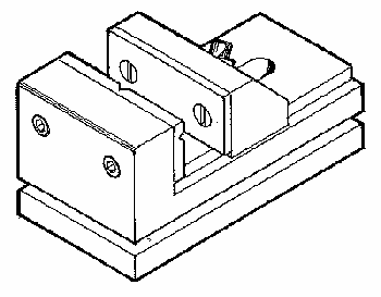

The most convenient way to hold small parts for milling is the Milling Vise. Milling vises are different from other machine vises in that they are designed to hold the movable jaw down while clamping, eliminating any chance for the jaw to lift. A cheap drill press vise is almost useless on a milling machine because you can't accurately align the machine to it.
The SHERLINE Milling Vise is sized just right to be the perfect working companion to the SHERLINE Milling Machine. The jaws are 1.50" (38.07mm) wide by 1.00" (25.38mm) deep and open a full 2.00" (50.76mm). the fixed jaw has both a horizontal and vertical "V" groove to facilitate holding round bar stock. The vise comes complete with two clamps for use in attaching it to the milling machine. These clamps are the same as the 4-Jaw Hold Down Set (P/N 3058).
NOTE: To keep the surface of your table from being marred, we recommend you take a file and slightly soften or deburr all the edges of the angle clamps that contact the table.
The advantages of this vise are obvious when movement of the jaw is studied. (See Figure 1 and look at the bottom of your vice.) The tightening force (F1) produces not only a force against the part (F2), but also a force pulling the jaw downward (F3). Therefore, angle "A" must exceed 45° in order to make force F3 greater than F2. This keeps the movable jaw from "tipping" back. Also note that extreme clamping angles beyond 60° start to apply much downward pressure but not much horizontal force is directed to holding the part. Moving the pull-down barrel to the proper slot keeps the adjustment within the most effective clamping range.
To clamp a part, place the jaw in approximate position and start tightening the adjustment screw at an angle of 45° or greater. (The back face of the moveable jaw is machined at a 45° angle for reference.) If the angle of the adjustment screw gets up to 60° or greater and you still haven't drawn down on the part, loosen up the screw a little and move the pull-down barrel to the next slot and retighten.
CAUTION! Extreme vertical adjustment angles can allow the 10-32 x 1-3/4" adjustment screw to be driven into the surface of the table, damaging both screw and table. Therefore, the vice comes assembled with a 1-5/8" screw that is usable for most settings. To enhance adjustment to the longest ranges, change to the 1-3/4" screw provided.
Figure 2 shows the proper way to hold a part in the vise. If the part cannot be centered, use a spacer to help keep the jaws parallel. This vise has been designed to accurately hold objects being machined. It is not recommended for use as a bench vise or for clamping parts in such a way and with such force as to adversely effect its accuracy.

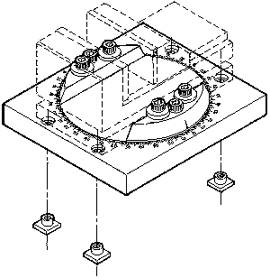
The P/N 3570 rotating mill vise base holds the mill vise and allows it to be rotated using an accurate laser engraved angle scale for reference. To read the instructions for the rotating base, click on the underlined name above.
FIGURE 1-below left, is a cross-section which shows the
pull-down bar located in the center detent of the vise body.

FIGURE 2- above right, shows the right and wrong way to hold a work piece in the vise.
|
REF. NO. |
PART NO. |
DESCRIPTION |
|
1 |
35100 |
Vise Body |
|
2 |
35020 |
Movable Jaw |
|
3 |
35030 |
Fixed Jaw Insert |
|
4 |
35040 |
Movable Jaw Insert |
|
5 |
35120 |
Pull-Down Member |
|
6 |
35060 |
Convex Washer |
|
7 |
35070 |
Flat Head Screw, 6-32 x 3/8 (2) |
|
8 |
30561 |
T-Nut, 10-32 (2) |
|
9 |
35580 |
Hold Down Clamp (2) |
|
10 |
40330 |
Skt Hd Cap Screw, 10-32 x 5/8" (4) |
|
11 |
35130 |
Skt Hd Cap Screw, 10-32 x 1-5/8" |
|
12 |
40700 |
Skt Hd Cap Screw, 10-32 x 1-3/4" |
RETURN TO ACCESSORIES MASTER LIST
Shop for Sherline LATHES
Shop for Sherline MILLING MACHINES
RETURN TO My Home Page
| Home
Page | Frequently
Asked Questions | Testimonials
| Lathes
|
| Mills
| Accessories
|
Tool
Prices | Accessory
Prices |