Table diameter: 4.0" (102mm)
Table height: 2.0" (51mm)
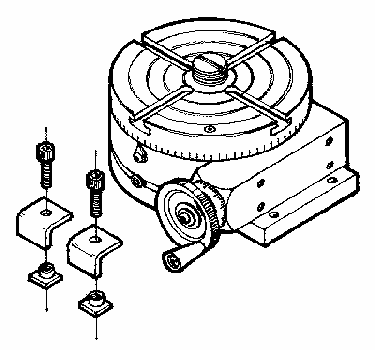
Sherline Products’ rotary table is 4" (100mm) in diameter and has been designed to be used in conjunction with our vertical mills; however, it can be easily adapted to any equipment where size and configuration would make it useful. It has a worm ratio of 72-1 making one revolution of the handwheel 5° of table movement. The table has been engraved with 5° lines identified every 15°, and the handwheel has 50 graduations making each graduation 1/10° allowing a circle to be divided into 3600 parts without interpolating. The table can be locked by tightening a set screw. (Reference number 24 in the exploded view at the end of this page.)
The T-slots accept Sherline 10-32 T-Nuts (P/N 3056 or 4025). The weight of the rotary table is 7 pounds and it stands 2" (50mm) high; it has been built of bar stock steel. A set of hold-down clamps (P/N 3058) is provided with the chuck to mount it to the mill or lathe table.
NOTE: To keep the surface of your table from being marred, we recommend you take a file and slightly soften or deburr all the edges of the angle clamps that contact the table.
A right angle attachment (P/N 3701) is available. This has been designed with an adjustment to align the table perfectly vertical. See optional Sherline right angle attachment (P/N 3701).
An adjustable right angle tailstock (P/N 3702) is also available to allow you to turn a part between centers using the rotary table, right angle attachment, and adjustable right angle tailstock.See optional Sherline adjustable right angle tailstock (P/N 3702).
The following instructions have been written to show what's involved in doing a complex job accurately. I believe if you truly understand the job I will describe in detail, average jobs will be accomplished without filling your trash can with mistakes. Remember, there are not many people capable of making the complex machined products used today, and if you can master the vertical mill and the rotary table combination, you will have come a long way at becoming a good machinist. You will find erasers aren't much good and no one has come up with a good "putting on" tool when it comes to metal parts. Complex parts are very difficult to make. When you're making "one-of-a-kind" parts, don't worry how long it takes; spend your time planning and checking so you don't have to worry about starting over.
When a rotary table is put on a vertical mill you end up with a machine that is theoretically capable of reproducing itself. This means the capabilities of your Sherline mill are governed by the size of the part and the ingenuity of the operator. The purpose of these instructions is to give you an insight into properly using this accessory. An inexpensive calculator with trig functions is a must for complex jobs. Standard milling machine set-ups usually involve aligning the work with the table and then with the spindle. This is easily accomplished because the table can be accurately moved with the handwheels. Aligning a part on a rotary table can be very trying because the work has to be clamped into position. When you consider the fact that the part turns, a .001" (.03mm) error in location gives a .002" True Indicated Run-out (T.I.R.) when checked with a dial indicator.
Many times it is advisable to start by doing the rotary table work first which can eliminate precision aligning. A quick way to align the milling spindle with the rotary table is by indicating the hole in the center of the rotary table. Next, prick punch or spot drill the center on the work you wish to have line up with the rotary table. Put a pointer in the spindle that runs true. Set the work under the spindle and lower the head until it engages with the center mark, then clamp the part down. You now have the work reasonably aligned with the rotary table and spindle. At this time, rotate the table with the spindle running and the pointer slightly backed off. If the part is properly aligned, the pointer should always line up with the center mark, and you should write down your handwheel settings. It is also advisable to write an "R" or "L" after the handwheel setting to remember which way the backlash was set.
Enclosed with your rotary table is an adapter (P/N 3709) that allows a Sherline chuck to be screwed directly to the table. This allows work that is of the correct size and configuration to be quickly aligned with the rotary table with reasonable accuracy. Be sure to consider the fact that a mill cutter could unscrew a 3- or 4-Jaw chuck held on in this fashion (See Figure 1). Use only very light cuts when this adapter is used. If you believe this could be a problem with your set-up, add a second clamp to eliminate the possibility of the chuck unscrewing from the adapter.

FIGURE 1—Cutter and Chuck directions of rotation.
The ball game changes when you want perfection, and this is true whether you are working with an inexpensive Sherline machine or a $20,000 mill. You can't expect to work within .001" unless you have your machine square. On the Sherline, a few shims and a dial indicator should get your machine square if you have something square to work to, preferably a small precision square. There is no adjustment for X-axis in relation to Y-axis, but this has been machined accurately. The vertical slide should be square with the table and the head and spindle should be square with the vertical slide. Remember that the size of the part has a lot to do with how square the machine has to be.
The first place to start to align your Sherline mill is to run an indicator on the work table to check for flatness. Move the X- and Y-axes independently to determine any error. These errors can be easily eliminated by placing a shim under the rotary table so the table runs perfectly true. Normally, this isn't necessary, but we are talking about "perfection".
To align the vertical bed with the X and Y slides, clamp something to the table that you are sure is square. With an indicator mounted to the head, move the head up and down a couple of inches with the indicator reading a known square that is set up to read in the X-axis direction. With the 4 screws that hold the steel bed to the column block, adjust the bed until there is a minimum indicator movement. The Y-axis direction can be corrected with a shim between the column block and the mill base using the same method.
With the vertical bed aligned with the base, the head can be aligned to the rest of the machine by "sweeping" the head in. The rotary table will give a good surface to indicate in. Clamp the indicator in the spindle as shown in the mill instructions that came with your mill. The head should be fairly square but can be improved upon by using the slight amount of play on the alignment key to square it up on the X-axis and a shim between the head and saddle (if needed) on the Y-axis.
In most cases the job can usually be done without going through the process outlined and using the machine as it comes. I'm only trying to educate you to what it takes to work at a precision level of machining. Any toolmaker worth his salt would not attempt to build a close tolerance part without first squaring the spindle of a vertical mill.
A close look at Figure 2 below will start making you aware of the complexities of working with a rotary table. Unless you are doing a hole layout, you very seldom can work with the angles and dimensions on your drawing because of the cutter diameter.

FIGURE 2--A demonstration of CPR or Cutter Path Radius.

FIGURE 3—Cutter machining outside of part.

FIGURE 4—Cutter machining inside of part.
Sherline now offers adjustable "zero" handwheels for our lathes and mills.This makes calculation of the feed much easier as the handwheels can be reset to "zero" each time. If you do not have the resettable handwheels, the job simply requires a bit of note taking. If you get into the habit of writing your handwheel setting down and calculating movements, it's really not bad. A piece of tape stuck along the edge of the mill table and mill base with a mark that shows starting and finishing points can be of considerable help. Of course, you will still have to use your handwheel numbers, but the marks will make you aware they are coming up. Counting the turns of a handwheel on long movements can have disastrous results if you're distracted and turn one too many. One of our customers attached scales (rulers) to our mill on both the X- and Y-axes, which I always thought was a good idea. (Our deluxe mill, P/N 5400/5410 now incorporates laser engraved scales on table and base.) If you have trig tables or a calculator with trig functions you can take a lot of the guesswork out of exact locations and angles.
The next problem you must be aware of is why the rotary table must be offset to cut segments. Study Figure 6 and it becomes obvious that allowing for the cutter diameter at one end of the segment will not make any correction at the other.

FIGURE 5—This example shows how easy it is
to allow for the cutter diameter using trigonometry.

FIGURE 6—Offsetting the rotary table to cut segments.
When one of our customers purchases their first metal cutting tool, it is usually a lathe and somewhere in that customer’s mind is a brass canon he now has an opportunity to build. When a customer buys his first rotary table, chances are they either want to drill hole patterns which shouldn't require any instructions or make some kind of wheel with spokes in it. Therefore, I will describe how to "accurately" cut a wheel with spokes. I realize that in most cases it is not necessary to work to this degree of accuracy to do a job of this nature, but to accurately make a precision part of this type is what a rotary table is all about. In most cases, I will leave you to your own common sense as to the depth of cuts and how much to leave from roughing and finish cuts. Remember, I have never seen a part scrapped from taking too light of a cut. Make an accurate drawing at the start showing offsets and cutter paths (similar to Figure 7). The offsets can be calculated as shown in the sample in Figure 7 below.

FIGURE 7—Drawing and calculations for cutter paths.
REMEMBER...the rotary table center must be precisely located below the spindle when you start. Only one half of the segment may be cut from the calculated point, which is why only one half of the spoke width is considered. Look at the drawing again and be sure you truly understand why you can only cut one half of the segment before proceeding or your chances for success will be dismal.
Now we have the offsets calculated and the rotary table "indicated in" in relation to the spindle. We move the X-axis the amount of the offset moving the table to the left. Be sure to consider the backlash, and it may also be prudent to allow for roughing and finish cuts. Now move the Y-axis and the Y offset in (towards the column). This will allow the first half of the segment to be cut so that it looks like the diagram. Assuming the part is properly clamped to the rotary table and held in such a way that you can't inadvertently cut into the table, it's time to start. The example has 4 equal segments which means a spoke will be cut every 90°; therefore, a lot of confusion can be eliminated if you start with your table at 0° (see Figure 8). The center of the spokes will now lay out at 0°, 90°, 180°, and 270°, and the halfway point will be at 45°, 135° etc. Allowance for the cutter was taken care of when the offsets were calculated. It is not necessary to calculate the value of angle "A" or other angles because you are only cutting one-half the segment at a time.
A good rule now is to take a very light cut (.001") and convince yourself everything is correct. The real trick of machining is to do something you have never done before the "1st time", and you can't be too careful. A one-minute check versus three hours or more to start over makes this a good investment in time. The cut along the spoke is accomplished by moving the X-axis only back and forth using the calculated points until you get through the part, and again I remind you it may be wise to take a roughing cut. Sometimes an undersize (resharpened) end mill is a good way to rough cut and then change end mills for finish passes. This allows the same handwheel number used for roughing and finishing.
The rotary cuts are made with the X-axis in its proper position, and the table rotated counter clockwise. One of the real neat things in machining happens when using a rotary table to feed work into an end mill, and I believe it comes about because of the slow and precise feed that can be obtained. If a hole you're cutting requires a bottom, great finishes can be had from end mills and rotary tables. The rotary part of the segment only needs to be moved slightly past the half way point for the remainder of the segment will be cut with the Y-axis offset moved out from the column and the table rotated in a clockwise direction.

FIGURE 8—Completing the spokes of a wheel.
It's quicker to cut the first half of all 4 segments, then move the Y offset and complete the segments. If you're going to try something like this for a first project, check your entire plan out with .001" cuts and be positive you're correct before making cuts that could scrap your part
I'm going to leave it up to you to determine when you know enough about gears to try and produce one. One of the best sources for information on gears is Machinery's Handbook. Gears are built to a rigid set of rules, and they are more complex than you might imagine.
I will only try to explain how to cut a simple, low tolerance gear. You will also have to determine the blank size, depth of cut, RPM of the spindle and so on. If you successfully cut a good gear on your first attempt, be very proud of yourself. It can be frustrating if you are not organized.
Gears can be cut using a rotary table with a reasonable amount of precision. In many cases, gears--even inexpensive ones--are very precise. Gears are usually produced by "hobbing". This method uses a cutter that is similar to a worm gear. The teeth are generated with both the cutter and the blank turning. In fact, the process looks just like a worm gear running. Methods like this produce perfectly shaped teeth that are perfectly spaced. It may be theoretically possible to produce a perfect gear one tooth at a time, but your odds of success are dismal if this is the type of gear that is required. I suggest you stick with "clock" type gears for your first few projects.

FIGURE 9—A sample setup for cutting a gear. The small inset (upper left) shows
the column moved back to the rear hole to allow clearance for cutting larger diameters.
Cutters can be purchased that will produce a fairly good tooth form, but they are expensive and have a very limited range. A cutter can be ground that works like a fly cutter. Use our P/N 3217 for this. A 1/4" lathe tool blank is provided which fits this holder. Use the damaged gear you are replacing for a shape reference to grind the tip of the cutter. The corners on a bench grinder wheel are used to generate the shape on the tool blank. At first it may seem almost impossible to do this, but it is not. Just keep checking the tool to a gear that can be used for a gauge by holding the two up to a light source. You'll find that the final grinding is done by "feel". Lathe tool bits are cheap and available, so it is a process worth learning. When the tool is mounted in the holder, don't allow it to stick out any more than necessary. Figure 9 above shows a typical setup. A tailstock isn't always necessary. Remember, the gear blank must run true before starting.
To figure the amount to move between cuts, an electronic pocket calculator is very helpful. Simply divide 360° by the number of teeth you wish to cut. This will give you an answer in degrees and tenths that can be used directly on your rotary table without conversion to degrees, minutes and seconds. Your rotary table is calibrated directly in degrees and decimal divisions of a degree. (Each mark on the handwheel is equal to 1/10°.)

FIGURE 10--Degree calculations and handwheel settings
for making the first four cuts on a 29-tooth gear.
The reason you should divide then multiply each time is if you "rounded off" on the first division, your error would build up by the number of teeth you were cutting. If your pocket calculator has a memory function there is an even easier method of calculating each cut. Simply store the first in memory and add it to itself each time. Because the calculator stores the number to even more decimal places than it displays on the screen, the answer is usually so accurate the 29th calculation should yield almost exactly 360°.
Joe Martin, President and Owner
Sherline Products Inc.
 of the rotary table in Solid Edge by
Sherline's John Costello shows
some of the in internal components in
relation to each other.
of the rotary table in Solid Edge by
Sherline's John Costello shows
some of the in internal components in
relation to each other.

|
REF. NO. |
PART NO. |
DESCRIPTION |
|
1 |
10930 |
3/8" Bearing |
|
2 |
30560 |
T-Nuts, 10-32 |
|
3 |
31080 |
Set Screw, 10-32 x 3/8" |
|
4 |
35580 |
Hold Down Clamp |
|
5 |
37090 |
Chuck Adaptor |
|
6 |
37100 |
rotary table Base |
|
7 |
37110 |
Table |
|
8 |
37120 |
Worm Housing |
|
9 |
37130 |
Worm Gear |
|
10 |
37150 |
Oiler |
|
11 |
37160 |
Preload Nut |
|
12 |
37170 |
Lock Pin |
|
13 |
37180 |
Upright |
|
14 |
37190 |
Right Angle Base |
|
15 |
37200 |
Button Hd Skt Hd Cap Screw 10-32 x 3/8" |
|
16 |
37210 |
Hold Down Tab |
|
17 |
37220 |
Button Hd Skt Hd Cap Scrw,6-32 x 1/4" |
|
18 |
40050 |
Handwheel Assembly |
|
19 |
40330 |
Skt Hd Cap Screw, 10-32 x 5/8" |
|
20 |
40340 |
Skt Hd Cap Screw, 10-32 x 1" |
|
21 |
40420 |
Headstock Bearing |
|
22 |
40510 |
Skt Hd Cap Screw, 10-32 x 3/8" |
|
23 |
40520 |
Cup Point Set Screw, 10-32 x 3/16" |
|
24 |
40540 |
Cone Point Set Screw, 5/16-18 x 3/4" |
|
25 |
40660 |
Washer, 3/16" I.D. |
|
26 |
40670 |
Skt Hd Cap Screw, 10-32 x 1/2" |
|
27 |
50120 |
Pointer |
RETURN TO ACCESSORIES MASTER LIST
Shop for Sherline LATHES
Shop for Sherline MILLING MACHINES
RETURN TO My Home Page
| Home
Page | Frequently
Asked Questions | Testimonials
| Lathes
|
| Mills
| Accessories
|
Tool
Prices | Accessory
Prices |